Handy guide to installing your new Bridge-in-a-Box modules
1 GB
2 GB
Step 1
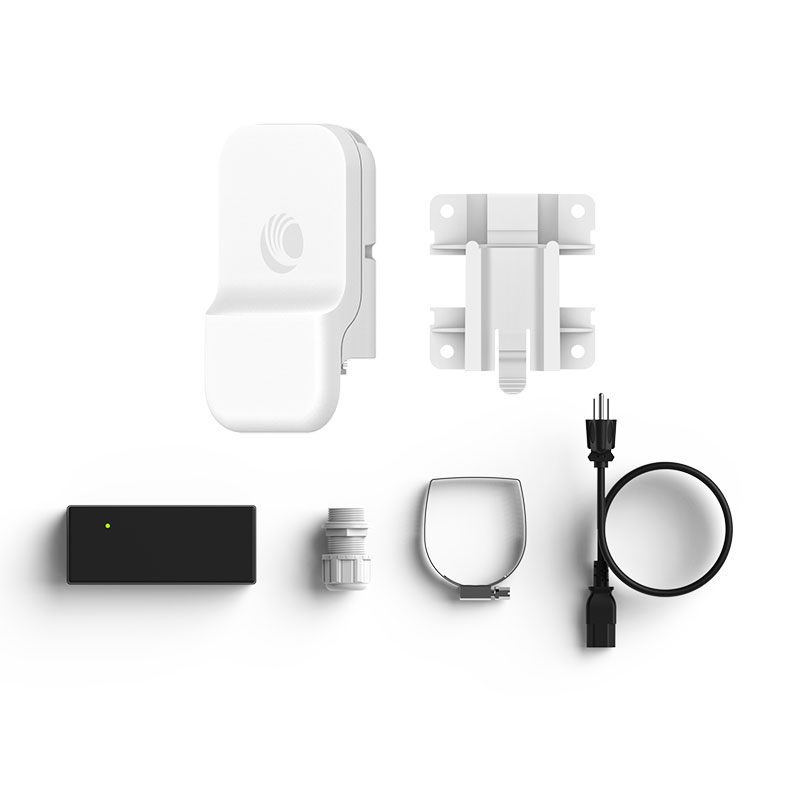
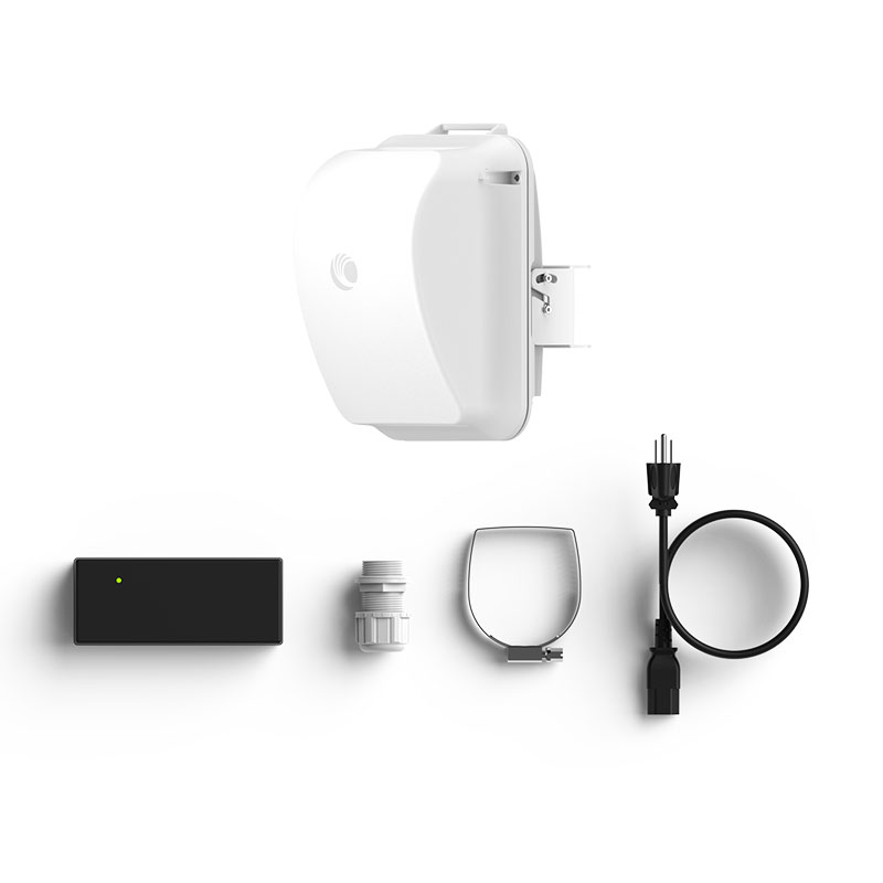
Attach bracket to the pole using the pole mount, adjust the position and mount the device securely.


Step 2
Attach the Ethernet cables to the port and secure the cable gland. Attach the grounding cable.


Step 3
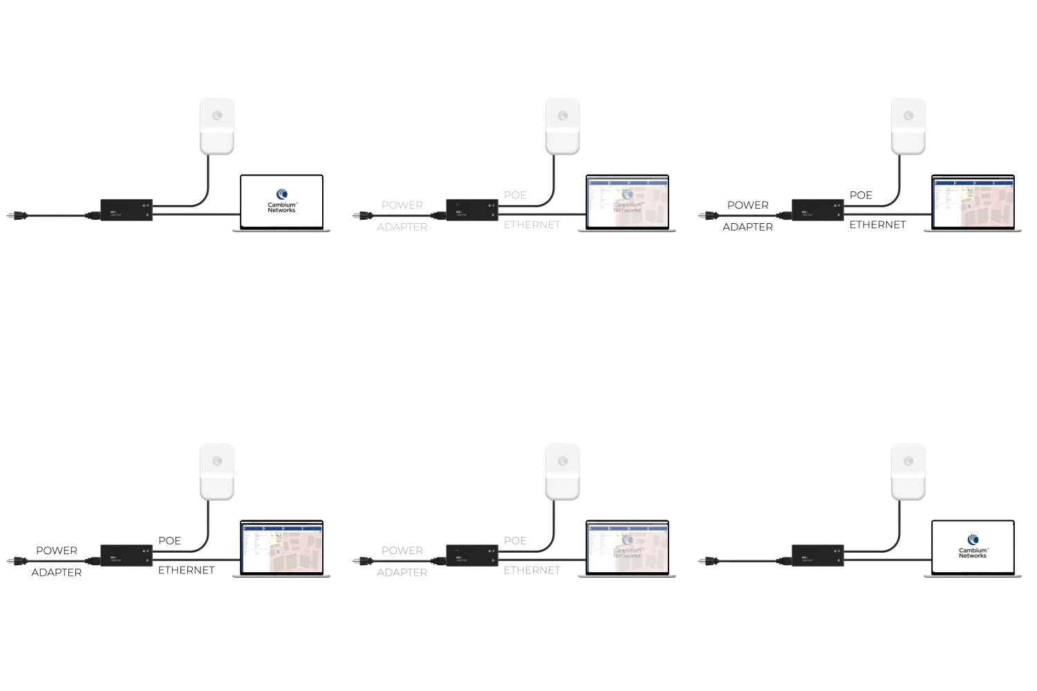
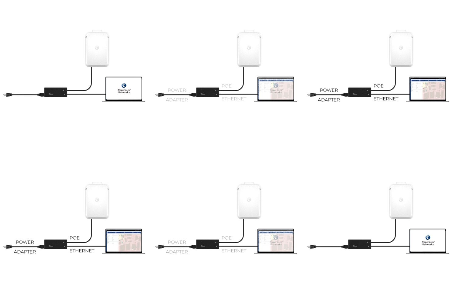
Connect the POE with module
Step 4
Establish Connection
Step 5
By default, the Bridge-in-a-Box modules are pre-configured and pre-paired to connect easily. You can log on to the device user interface (UI) using the default IP address (169.254.1.1 for the Controller node and 169.254.1.2 for the CN node). You can view the connected Controller and CN details on the Topology page of the device UI.
